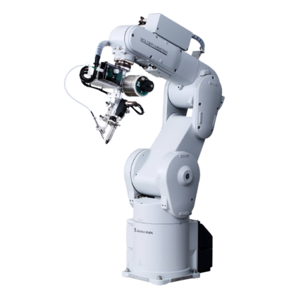
JC-3A00-0T3 | JC-3A00-0H3 | JC-3B01-0H4 | |||||
Number of Axes | 3 Axes Synchronous Control | 3 Axes Synchronous Control | 4 Axes Synchronous Control | ||||
Stroke | X Axis(mm) | 200/300/400/500/600 | 300/400/500/600 | 300/400/500/600 | |||
Y Axis(mm) | 200/300 | 200/300/400/500 | 200/300/400/500 | ||||
Z Axis(mm) | 50/100/150/200 | 50/100/150/200/300 | 100/150 | ||||
R Axis(deg) | – | – | ±360 | ||||
Drive Motor | Stepping Motor | Stepping Motor | Stepping Motor | ||||
X Axis | Feedback Control | Feedback Control | Feedback Control | ||||
Y Axis | |||||||
Z Axis | Open Loop Control | ||||||
R Axis | – | – | |||||
Maximum Portable Load |
Tool(kg) | 4 | 8 | 3 | |||
Maximum Speed <PTP Movement> *1 |
X-Axis Stroke | 200 300 400 |
500 600 |
300 400 |
500 600 |
300 400 |
500 600 |
X Axis(mm/s) | 700 | 800 | 700 | 800 | 700 | 800 | |
Y Axis(mm/s) | 800 | 800 | 800 | ||||
Z Axis(mm/s) | 400 | 400 | 400 | ||||
R Axis(deg/s) | – | – | 900 | ||||
R Axis Acceptable Moment of Inertia (kg・cm2) |
– | – | 90 | ||||
Repeatability(mm)*2 | X Axis(mm) | ±0.02 | ±0.02 | ±0.02 | |||
Y Axis(mm) | ±0.02 | ±0.02 | ±0.02 | ||||
Z Axis(mm) | ±0.02 | ±0.02 | ±0.01 | ||||
R Axis(deg) | – | – | ±0.008 | ||||
External Dimensions (excluding cables and protrusions) W x D x H(mm) |
Robot | W:Y-Axis Stroke + 319 D:X-Axis Stroke + 309 H:Z-Axis Stroke + 357 |
W:Y-Axis Stroke + 426 D:X-Axis Stroke + 309 H:Z-Axis Stroke + 357 |
W:Y-Axis Stroke + 426 D:X-Axis Stroke + 309 H:Z-Axis Stroke + 334 |
|||
Controller | 170 x 310 x 300 | ||||||
Mass(kg) | Robot | Varies depending upon stroke combination. | |||||
Controller | 7.5 |
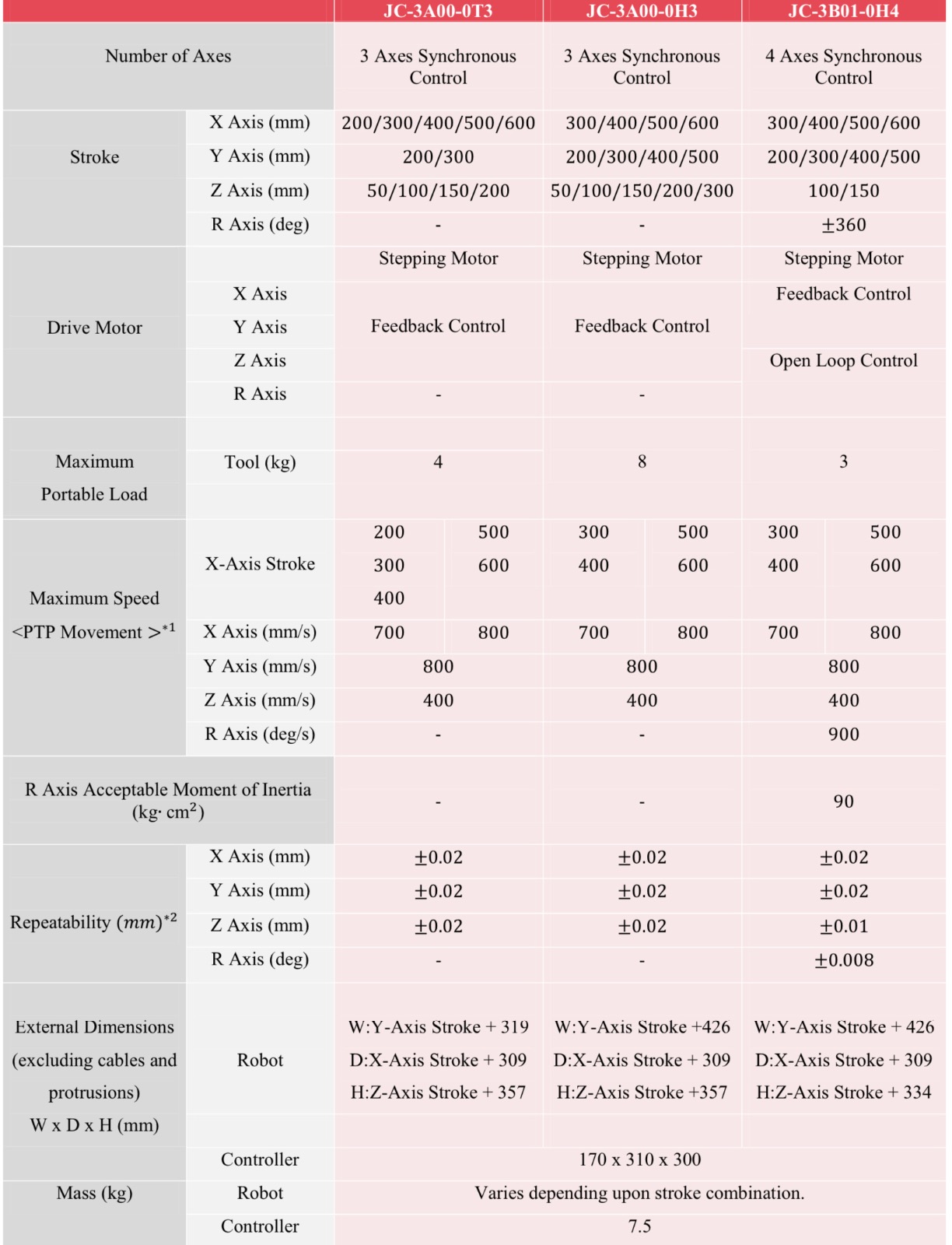
*1 This value reflects the maximum portable load when measured with all the axes assembled. For information about acceleration rates, please refer to the speed & acceleration materials in the Catalogue section of our Catalogue and Diagram Download page. Maximum speed may be unreachable depending upon the tool attachment setup. The X and Y axes individual unit speed and acceleration are 800mm/s and 5000mm/s2 respectively.
*2 Repeatability measured at a constant temperature, so absolute precision is not guaranteed.
These values are for standard models and may differ with specification modifications.
Please contact us for details
Common Specifications
Control Method | PTP (Point to Point) control, CP (Continuous Path) control | |
Interpolation | 3-dimensional linear and arc interpolation | |
Teaching Method | Remote Teaching (JOG)/Manual Data Input (MDI) | |
Teaching System | · Direct teaching using the optional teaching pendant
· Off-line teaching with JR C-PointsⅡ software from a PC. Compatible for use with CAD-made graphic data (DXF, Gerber, jpeg). |
|
Teaching Pendant Display |
Measurement Units | mm/inch |
Languages | Switch back and forth among these languages: Japanese・English・German・Italian・Spanish・French・Korean・Simplified Chinese・Traditional Chinese・Czech・Vietnamese. | |
Program Capacity | 999 programs | |
Data Capacity | Maximum 32,000 Points*3 | |
Simple PLC Function | Maximum 100 Programs 1,000 steps/Program | |
External Input/Output | I/O-SYS*4*6 | 16 Inputs, 16 Outputs |
I/O-1*4*6 | 8 Inputs, 8 Outputs | |
I/O-MT (optional) |
for auxiliary axes (pulse string input type*8) control, control up to 2 axes |
|
Fieldbus (optional) |
Choose CC-Link, DeviceNet, PROFIBUS, EtherNet/IP, PROFINET or CANopen | |
COM Port (RS232C) | COM1, COM2, COM3: for external device control | |
MEMORY Port | For USB memory connection
· Read out and save teaching and customizing data · Upgrade system software · Update model settings data |
|
LAN*5 | For PC connection via the Ethernet
· Robot control via control commands · Connection to (optional) PC software “JR C-Points II” |
|
TPU | Dedicated teaching pendant (optional) connector | |
SWITCHBOX | Dedicated switchbox connector | |
EMG OUT | For external safety circuit connection*9 | |
I/O Built-in Power Supply (optional) | DC24V | |
Power Source | AC90~240V (single phase) 50/60Hz + external DC48V (depending upon facility supply) *7 |
|
Power Consumption | 150W (AC Power Supply) 300W (DC48V, motor drive power supply) |
|
Operating Environment | Operating Temperature | 0~40℃ |
Relative Humidity | 20~85% (without condensation) | |
Elevation | Up to 1,000m |
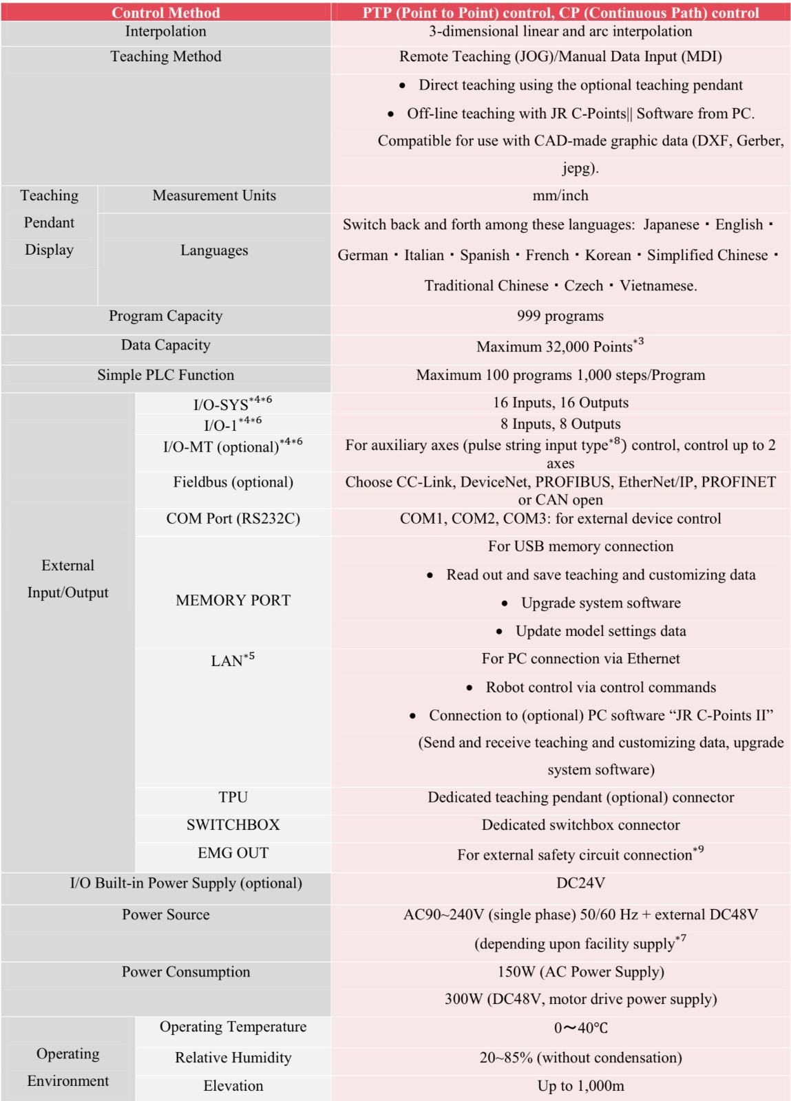
*3 Point data capacity reduces as the total function data setting/point job data/sequencer data increases, due the shared data storage area.
*4 When using an internal power supply, an (optional) built-in I/O power supply is required.
*5 LAN connection is 10BASE-T, 100BASE-TX.
*6 There are two types of I/O polarity: NPN specifications and PNP specifications.
*7 With the 4 Axes Specifications, the XY Axes are powered externally at 48V, while the ZR Axes use a 24V control power supply.
*8 We ask customers to please prepare their own control power supply, pulse motor and motor driver.
*9 We ask customers to please construct their own safety circuit.
We ship the robot disassembled, packing each axis as an individual unit.
Please assemble the robot upon delivery. In addition to the specifications listed above, other specifications may also be available.
Please contact us for more information.
Optional specifications are available only when placing your order; no post-order modifications.
Specifications may change without prior notice to improve product quality
Standard Accessories
- Power Cable
- TPU Short Connector
- SW-BOX Short Connector
- EMG-OUT Connector
- Box Mounting Plate
- Operation Manual (CD-ROM)
Optional Attachments
- Teaching Pendant
・With Emergency Stop Switch
・With Emergency Stop/Enable Switch
- Switchbox
・With Initialization Switch
・With Initialization Switch/Mode Changing Switch
・With Intialization Switch/Purge Switch
・With Initialization Switch/Mode Changing Switch/Purge Switch
- Cable Set (for robot to controller connection: 3m/5m)
- Cable Carrier Set (for X Axis/Y Axis)
- I/O-SYS cable, I/O-1 cable
- Needle Adjuster
- PC Software JR C-PointsⅡ (WindowsR 7/ WindowsR 8.1/ WindowsR 10 compatible)
Reviews
There are no reviews yet.